
Auto Design - Conditioning
To access this task:
-
Activate the Design ribbon and select Pit Modelling >> Auto Design. Select the Conditioning tab.
-
Activate the Design ribbon and select Dump Modelling >> Auto Design. Select the Conditioning tab.
Note: All settings on this panel relate to the active pit design scenario only. Specified tapering values are stored per-phase; your settings can be independently configured for each phase of your pit or dump.
The Conditioning tab is used to configure how design strings for pits or dumps are fine-tuned in Auto Design tasks.
During automatic pit design, decisions need to be made where two regions of a pit (with competing design parameters) intersect. For example, two slope regions have been defined within the same pit or dump. The berm width for region 1 is 15m and for region 2 it is 30m. These two regions are adjacent, i.e. there is a common boundary.
There isn't a definitive method for creating a 'correct' result
with regards to how the boundary condition is managed. You could elect
to just change from one region setting to another on the boundary
itself (abruptly), for example: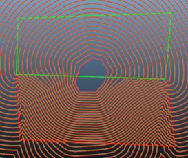
...or you could blend the design string changes between the regions, which could give a more pragmatic result.
The Conditioning tab allows you to control the way design strings are generated. If conditioning is applied, you need to specify the context within which it will apply (at the pit/dump level or one or more benches/lifts) and the type of conditioning to apply. You can choose to remove design strings that are generated below a certain area, or you can pre-simplify the data used to create design strings by removing data found to be in clusters (and potentially generating sharp direction changes that are unwanted). You can also choose a filleting radius (inside and / or outside arc - which is governed by your design approach).
The aim of this panel is to provide parameters to the design string generation function so that the specified road definition and slope region settings are applied appropriately.
For example, a string that is formed of several near coincident vertices could give rise to a wide range of potential azimuths along its length and conditioning removes the unwanted data, creating a simpler geometry that does not unexpectedly trigger the influence of predefined rosettes.
For pit designs, Conditioning tab values are stored per-phase; your settings are independently configured for each phase of your pit. For dump designs, all design settings are stored for each independently-defined dump.
- Pit phases are defined using the Define Phases task.
- Dumps are defined using the Define Dumps task.
Activities
Configure String Conditioning Settings
To configure string conditioning for your pit or dump scenario:
-
Configure the berm tapering table by:
-
Manually entering per-bench or per-lift string conditioning settings into the table.
-
Setting up a rule to automatically populate the table using a pattern of instructions.
-
A combination of rule-based and manual methods.
To define a rule to update the conditioning table according to general constraints:
-
Choose the bench or lift range within which tapering constraints apply. Do this by setting the From bench and To bench fields, which are inclusive. For example, in open pit design, to apply tapering constraints from bench 1000 to 750 inclusive, enter "1000" and "750" accordingly.
Note: Open pit bench ranges are defined according to increasing depth, between the uppermost (From bench) and lowest (To bench) values. The opposite is true for dump design, where a range should be specified in dump lift order, from lowest to highest elevation.
-
Choose the frequency, within the specified range, that constraints are applied. For example, to define constraints every other bench, set conditioning values every 2 benches, set 1. Defining a periodic constraint can be useful where it is known that a catch bench exists at regular intervals either down the pit or up the dump.
-
Choose the type of conditioning control to be updated in the table below. This can be one of the following, which matches the available columns in the table:
-
Blending Distance - The distance over which changes in slope region constraints are applied between different regions.
-
Max. Width Change - The maximum berm width change permitted over a given distance around a pit or dump perimeter.
-
Max Slope Change - Constrain the amount a face angle can change over a given perimeter distance.
-
Minimum Area - Set a lower bound for removing design strings with a lower 2D area from the design,
-
Minimum Deviation - Pre-simplify the information that is used to generate design strings by specifying a straight-line distance.
-
Inside Fillet Radius - fillet the angle changes between string edges using an approach similar to fillet-string-points-berm.
-
Outside Fillet Radius - as above, but for outside string edges.
These constraint types are described in more detail further below.
Tip: Apply rule-based tapering conditioning values cumulatively to the table. For example, you can set the Blending Distance, then apply a Max. Slope Change (using the same or different pattern rules) by Applying each configuration successively.
-
-
Define the actual conditioning value for the selected control using the of field.
-
Apply the rule to the table below. For example, if designing a dump an Inside Taper Distance of 90 is applied to each alternate lift from 797 to 713 elevation, with no prior constraints applied, the table looks like this:
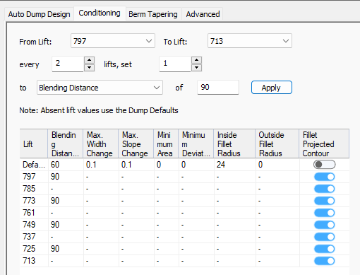
Note: The From Lift (or Bench) and To Lift (or Bench) settings default to the highest and lowest elevations detected, according to your current lift (or bench) definitions.
-
-
To manually edit the conditioning controls table:
- Review the Defaults table row. These tapering values are applied for all benches or lifts where a more specific conditioning rule has not been set (that is, where a "-" appears in the table below). You can adjust any of the following default values:
- Blending Distance:
Define a blending distance for the pit and/or bench(es). This
controls the distance over which conditioning between regions is applied.
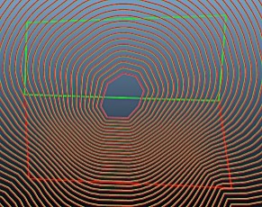
A blending distance of 0 indicates that no blending will be performed. Any blending distance value greater than 0 will average the values of the regions within that approximate distance of the point. In the introductory text above, the two images show the impact of a blending distance of 100m.
Here's an extension of the example above, showing the effect of different default (pit-level) blending distances across two regions as defined by boundary strings (using the Define Slopes task):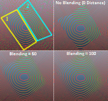
You can see that, outside the boundary string limits, the default slope region settings are applied. These will always be applied where more specific information on slope/width cannot be found within your current project.
Blending distance can also be set at the bench or lift level, using the lower table. These settings will always override any conditioning default values.
In the pit design example below, a blending distance of zero (no blending) has been set for two of the lower benches in a pit whereas a blending distance of 100 is applied at the pit level between the two regions that contain those benches:
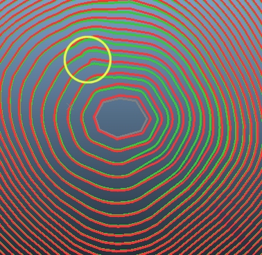
Where regions are defined, blending between regions is also controlled by the density of points that are used within each region boundary.
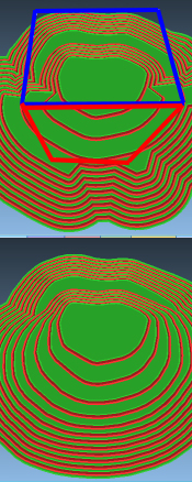
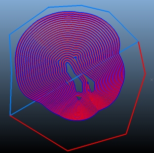
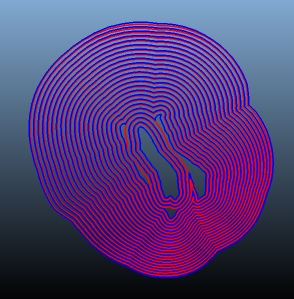
As a further example, the two images below show how a stark difference in berm width between regions can be smoothed. In both images, zone 1 (blue) is set to a berm width (standard) of 5m whilst zone 2 (red) is set to 65m. In the top image, a conditioning blend distance of zero is applied. The lower image shows the same pit calculated with a blend distance of 100m:
Max. Width Change: Define (either globally, or per-bench) the max berm width change that is permitted over a given distance around a pit or dump perimeter. This will be applied in addition to region blending, if specified. This "change control" is useful to enforce smoother transitions between regions requiring different berm widths.
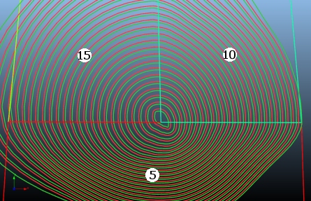
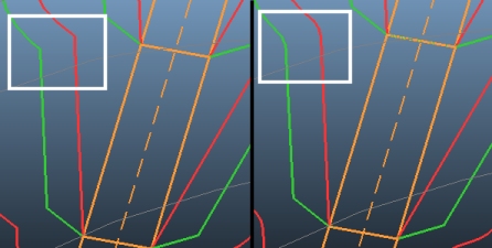
For example, in the image below, no blending has been set between the three pit regions shown by the rectangle outlines (these strings were used in the Define Slopes task to define the boundary of each region). The numbers in circles indicate the berm width:
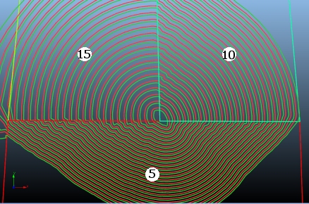
In this scenario, the design calculator will attempt to immediately adjust the berm width at the boundary of each region, whilst still maintaining other conditioning and berm tapering options (such as fillet radii, minimum area and deviation etc.).
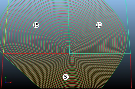
With slope region blending applied, the change between regions is more gradual, e.g:
However, in this example, it is possible for slope and width limits to be violated due to the presence of multiple regions influencing berm widths at or around the region boundaries. The presence of rosettes could compound this issue.
Applying change control to the berm width, either globally or per-bench, sets a constraint on the maximum width change permitted over a given distance. This is applied after region blending so can be considered a fail-safe mechanism. In the example below, the berm widths set by the region boundaries is honoured, but a Max. Width Change setting is applied:
In this example, this outcome is preferred as it generates a design that honours operational constrains between regions.
The default setting is absent (-) meaning no width control is applied; the berm widths will be influenced solely by design or slope region values (if they exist). You can also use a value of 0 (zero) which will ensure the entire bench ends up with the safest berm width.
Note: The Max. Width Change and Max. Slope Change parameters can only modify your pit design in safe manner; berms can only get wider and slope angles can only get shallower.
Max. Slope Change: This is similar to the Max. Width Change parameter described above, but is used to set a constraint on the amount a face angle can change over a given perimeter distance. As with the width control option, this can be applied at a global/pit level or per-bench.
For example, the image below shows a pit design with 2 slope regions (each with differing width and face angle constraints):
Decreasing the permitted Max. Slope Change induces a more gradual change between slope angles in both regions, as the constraint is applied (in this case) at the pit level, meaning all toe/crest strings must adhere to the "change control" for slope angles that is now in force, e.g.:
This parameter is also applied after slope region blending has been calculated, and can be used to prevent severe face angle changes that may be incurred as a result of multiple, competing region and/or rosette settings.Although pit design images are shown above, the same principles apply to dump designs controlled by regions and/or rosettes.
Note: The Max. Width Change and Max. Slope Change parameters will only be evident if pit sectors have been set up to require differing face angles or berm widths. If a single, global slope region definition exists for the whole pit (i.e. default values only), changing the width and slope conditioning parameters will not alter the current design string calculation.
Minimum Area: Design strings may be generated with an unacceptably low area (e.g. insufficient size to accommodate machinery or turning paths). This can happen where multiple projections converge, or at the pit/dump base, for example. Set a minimum area here and any generated string that has a 2D area lower will be removed from the design strings collection.
Minimum Deviation: Pre-simplify the information that is used to generate design strings by specifying a straight-line distance into this cell. Data points that are less than the permitted distance apart will be decimated to ensure a minimum spacing occurs. This will reduce the number of points used in the resulting design string and can be a useful way of removing unwanted jagged edges, dog-legs and/or near-coincident points which could trigger unexpected slope region control.
Inside/Outside Fillet Radius: Fillet the angle changes between string edges using an approach similar to fillet-string-points-berm. This command will fillet all coincident angles according to the values specified. The 'inside' nature of this setting is dependant on the mining direction and filleting will be applied in preference to 'pushing out' the pit wall wherever possible.
- Inside
Fillet Radius: This setting controls how design strings
behave when reach a change of direction. Using the same principles
as manual string filleting commands such as fillet-single-string-point
and fillet-string-points,
this setting can be used to control how the string on the inside
of the berm or outside of the berm are filleted. Whether this
is the pit or void side of the string depends on the string/design
direction.
For example, the image on the left below shows an unfilleted design (both inside and outside fillet radii are zero). The right-hand image shows an Inside Fillet Radius of 5 meters: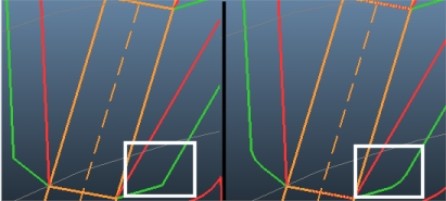
Outside Fillet Radius: Performs the same function as above, but on outside/convex string segments. For example, in the image below a top-down design is unfilleted in the left hand image but has an Outside Fillet Radius of 5 on the right:
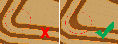
Another example, this time rounding off the impact of two constraint strings causing an intrusion into the pit void: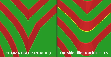
- Inside
Fillet Radius: This setting controls how design strings
behave when reach a change of direction. Using the same principles
as manual string filleting commands such as fillet-single-string-point
and fillet-string-points,
this setting can be used to control how the string on the inside
of the berm or outside of the berm are filleted. Whether this
is the pit or void side of the string depends on the string/design
direction.
Fillet Projected Contour: When a design string for a dump or pit has a significant change in direction, the Inside Fillet Radius and Outside Fillet Radius settings help enforce a practical shape. However, that shape may be good for the crest of a bench or lift but not necessarily for the projected toe string. Essentially, when the fillet radius is applied, the angle between the toe and crest could be different than the slope region.
The Fillet Project Contour toggle allows you to enable or disable filleting for individual bench or lift 'projections', meaning that:
In a bottom-up design you can turn on or off filleting for the crest strings, and;
for top-down designs you can turn on or off filleting for toe strings.
Consider the following example where filleting of individual lift projects is disabled (Fillet Project Contour is off) in the right hand image but enabled in the left hand image. All other design parameters are identical:
- Blending Distance:
Define a blending distance for the pit and/or bench(es). This
controls the distance over which conditioning between regions is applied.
- Review the Defaults table row. These tapering values are applied for all benches or lifts where a more specific conditioning rule has not been set (that is, where a "-" appears in the table below). You can adjust any of the following default values:
Related topics and activities